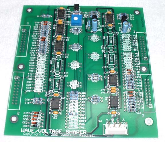 of the PCB with parts loaded
for the 3U MOTM panel version of this module. Not all components
are needed.
of the PCB with parts loaded
for the 3U MOTM panel version of this module. Not all components
are needed.This page describes the Diode Waveform Shaper module in MOTM format. The PC board was designed by Jim Patchell based upon a Tietze/Schenk universal piece wise linear function network, with input by myself (limit circuit, modulation inputs).
Here is the graphic file for the MOTM style front panel layout.
Note that this panel has modulation inputs but no modulation attenuators. If you intend on using the modulation inputs then I recommend building some of the Oakley Multimix modules. These are DIY kits that you'll have to assemble yourself, but are about the easiest ones you could do next to Paul's own modules. I recommend the Omeg pots sold by Oakley. Not only are the inexpensive, but the also come with brackets holding the pots to the front panel that make the PCB brackets unnecessary. The MOTM Stooges make 1U panels for these and are currently accepting orders. They also have instructions for making the Oakley Multimix into a triple reversable attenuator in addition to a three way mixer.
I toyed with the idea of adding the modulation attenuators but there were some concerns. These pots are expensive. They cost $5-$8 each, so the cost for four attenuators is $20-$32. The panel would have to be modified. It would either need to be increased to 4U wide, or use a non-standard, condensed knob format. The 4U wide is just too large for a feature that might not be commonly used and add to the panel cost. The condensed format would require special pot brackets, special artwork and a parts search for a smaller knob to make it work. With the Stooge panel deadline there really wasn't much time for this, and I figured it safer to stay with the existing MOTM format.
Cost of the 3U panel was $34 each plus shipping from the Stooges, but this price can vary. Check with them for the next run of panels.
The PC board from Jim Patchell is currently available from his web site.
You will also need a long 4 pot panel mounting bracket from the Stooges. These cost $4 each plus shipping.
Since this board uses only two positive and two negative breakpoint stages, not all of the components need to be loaded on the PC board. A Bill of Materials (BOM) will be posted at a later date showing which parts are needed. All parts are available from Mouser Electronics. I would consider putting together kits but will not build modules for others. The wiring can be labor intensive and it just isn't worth it for me.
A word about using this for modifying audio. To be honest, modifying a simple waveform may not be that interesting. It will often sound something like pulse width modulation. This can be made more interesting by using all four modulation inputs with different modulation sources for each one. The new MOTM-380 Quad LFO will be a good match for this board. Taking this one step further, another enhancement has been added to the MOTM panel. There are four additional OUT jacks. These jacks output the signals from the individual breakpoint stages. They are implemented using stereo switching jacks, so you can send each breakpoint stage to a different filter or processor, then feed it back into the internal summer of the DWS by using a Send/Receive cable. This type of cable has a stereo 1/4" jack on one end and two mono 1/4" jacks on the other. They are available at most musical instrument retailers. If you don't want to return the processed signal to the DWS then simply use a standard 1/4" mono patch cable and that input to the DWS summer will be grounded. Two main out jacks are included as they will often save you from using a multiple.
The modulation inputs modify the breakpoint of each stage, not the amplification. As noted before, these have no attenuators so you'll usually need an offboard attenuator such as on the Oakley Multimix.
Usage as a control voltage processor will be more common than as an audio processor. The number of stages included on the MOTM panel should be sufficient for most applications, and relieves the headache of setting 18 knobs for the full up design. It's a little known fact that one microprocessor based envelope module uses just three linear line segments to approximate logarithmic shapes. This module will be able to perform similar functions. Remember that these stages are additive, so knob setting can be tricky. I plan on posting settings of the most common transforms such as linear to log, log to linear, full wave rectification and more when my modules are constructed. Unlike a Wiard Mini-Wave, there will be no quantization artifacts from the transforms, and you will have modulation and knob control over them.
The breakpoint parameter sets the level at which the amplification occurs. For the positive breakpoints this is in the 0 to 10 volt range. For the negative breakpoints this is in the -10 to 0 volt range. The gain parameter sets the gain past the breakpoint. It can be positive or negative. Gain below the breakpoint is 1. The offset is just a DC bias control of the output. The results of each stage are then added back to a simple mixer. That's why I describe these stages as additive.
One application is to scale additional mod sources across the range of the keyboard. An example would be to have an LFO rate increase only in the middle of the keyboard.
Bill of Materials added in two formats, in Microsoft Word doc format with track changes mode on, so you can see changes from Patchell's BOM, or in text format. Updated to include four 1K resistors for stage outs.
Potential uses:
Wiring instructions for the front panel.
Photo of the PCB with parts loaded
for the 3U MOTM panel version of this module. Not all components
are needed.
Picture 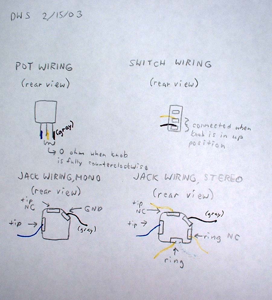 showing color
coding of connections to pots, switch and jacks.
showing color
coding of connections to pots, switch and jacks.
Picture (coming) showing color coding and designation of connections from PCB.
PCB Construction notes in html format, updated with information on resistors for OUT+ and OUT- jacks.
Special note: the power connector on the PCB is opposite of the normal MOTM configuration. That is, the alignment tab should face to the outer edge of the PCB, rather than inwards.
Link to mp3 file, using the DWS as a timbre modulator
Photo 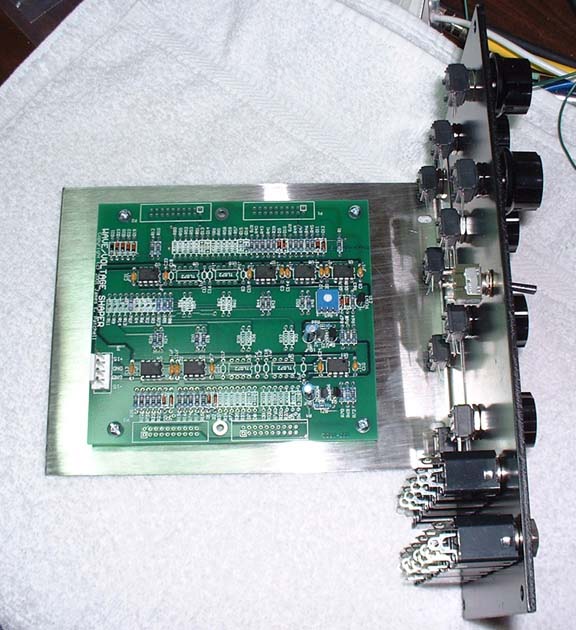 showing un-wired
pcb and front panel component mounting.
showing un-wired
pcb and front panel component mounting.
Photo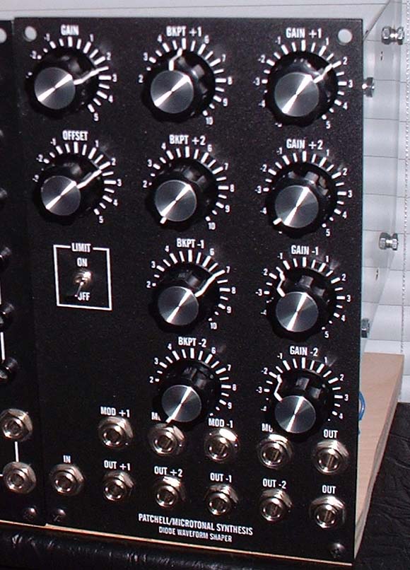 of the front panel.
Photo 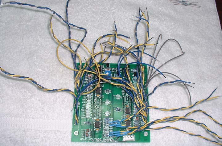 of the wired pcb.
Photo 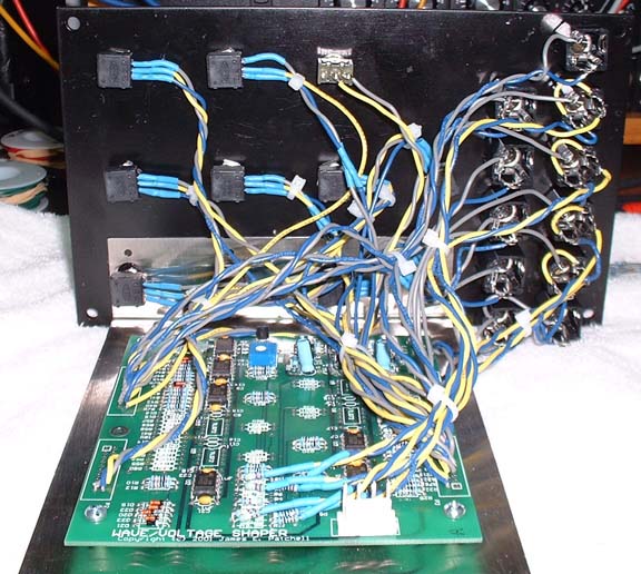 of the completely wired and
assembled module.
of the completely wired and
assembled module.
MP3s by Andrew Sanchez. Amazing vocal realizations.